RF Instruction Manual
2016-03-15 08:54:44
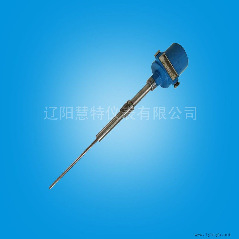
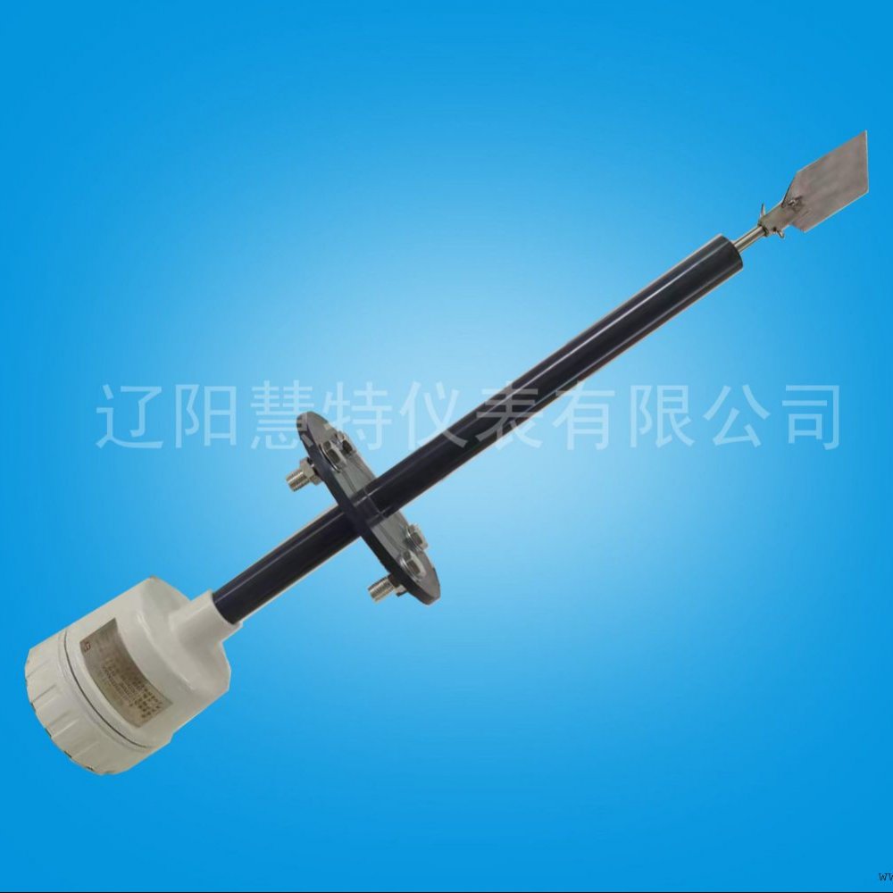
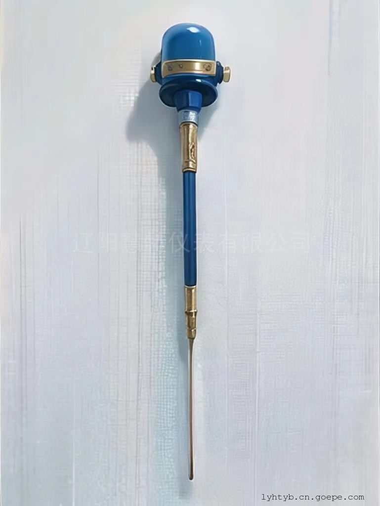
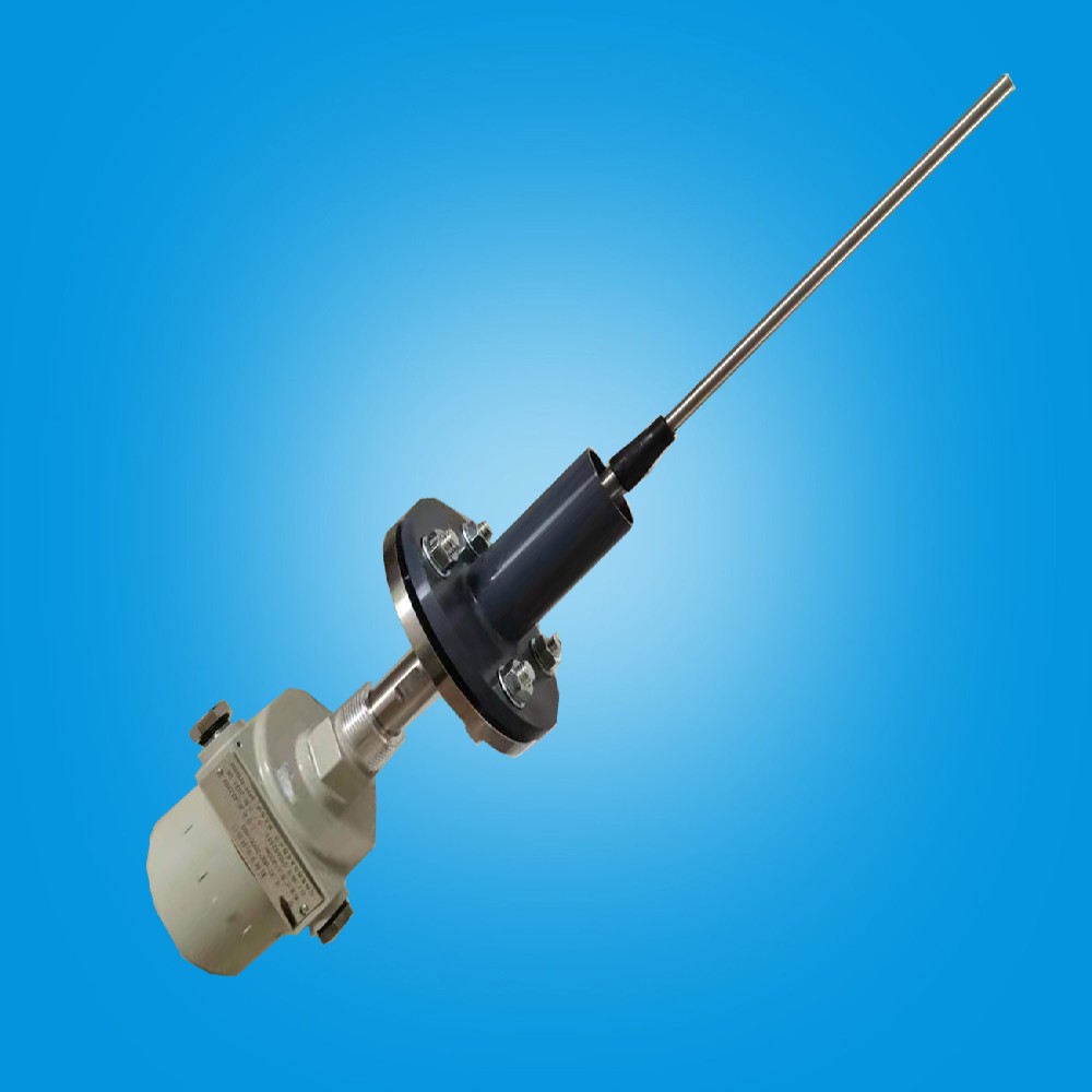
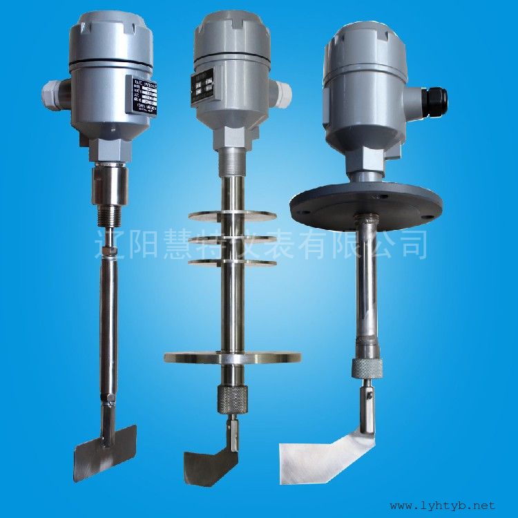
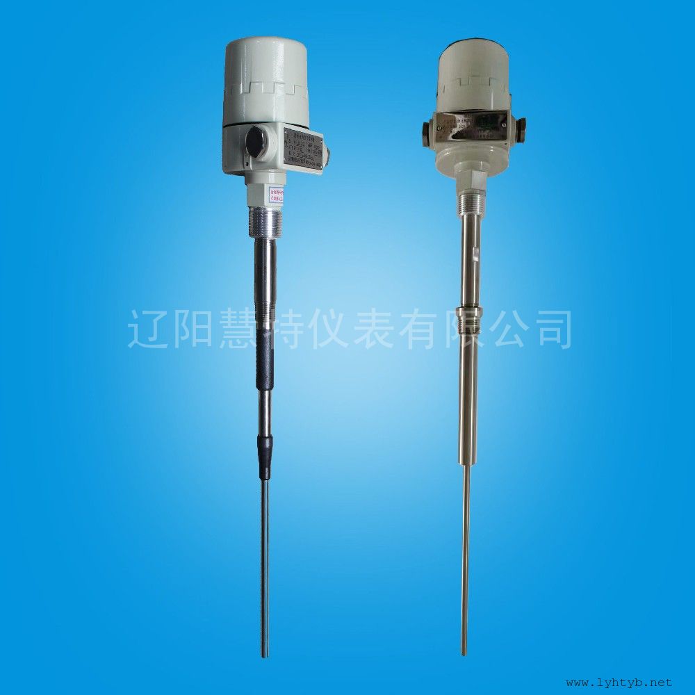
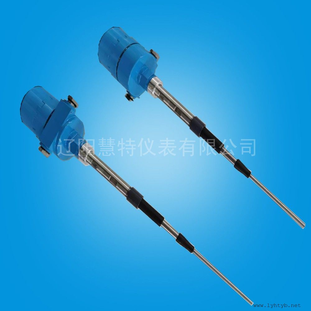
1 Material Level Meter Installation
1 Meter installation and site wiring should accord with national standard;
2 Power line and signal lines according to the wiring diagram, can not take the wrong;
3 To ensure the overall instrument grounding good, recommended the use of independent grounding wire;
1The instrument power supply must select instruments nameplate on the power supply voltage, the power supply will damage the instrument error.
2While the instrument power supply of 220VAC, L termination phase termination midline220V, N.
3And when the instrument power supply for24VDC," +" connected" -"24VDC cathode, anode terminal24VDC.
Special Reminder:220VAC AC and DC power supply of 24VDC instrument can not be used together, must be connected to the power supply before the reference junction label confirmed accurate after the ohmic.
L2000-24VDC Wiring Diagram:
Micro signal:lzh2014-0425
2 L2000-24VDC Calibration Method ( Alarm ):
1 Electricity, green LED indicator light;
2 In the absence of material short cases, the red LED indicator light is not bright;
3 Anti-clockwise slowly rotating RP ( sensitivity potentiometer ), until the red LED lights is bright;
4 By slowly clockwise rotation RP potentiometer, until the red LED lights just after the death and then according to the original direction of rotating half week ( according to the characteristics of the material );
5 According to the measured material dielectric constant size can continue to rotate clockwise or anticlockwise RP potentiometer to a proper angle, insulating medium 5~30 degrees, conductive medium 30~ 180degrees, to contact to the detection probe alarm output, the material is separated from the detection probe show normal status.
Micro signal:lzh2014-0425